


A quick introduction to OpenSCAD
Low-effort CAD like a programmerSo you want to use OpenSCAD...
I'm writing this post as a straight-to-the point guide to hand to people who need to make a basic shape or two for 3D printing. This guide assumes you already have OpenSCAD installed.
Basic shapes
OpenSCAD uses code to describe 3D objects. When you open a new project, you'll see a layout that looks roughly like this:
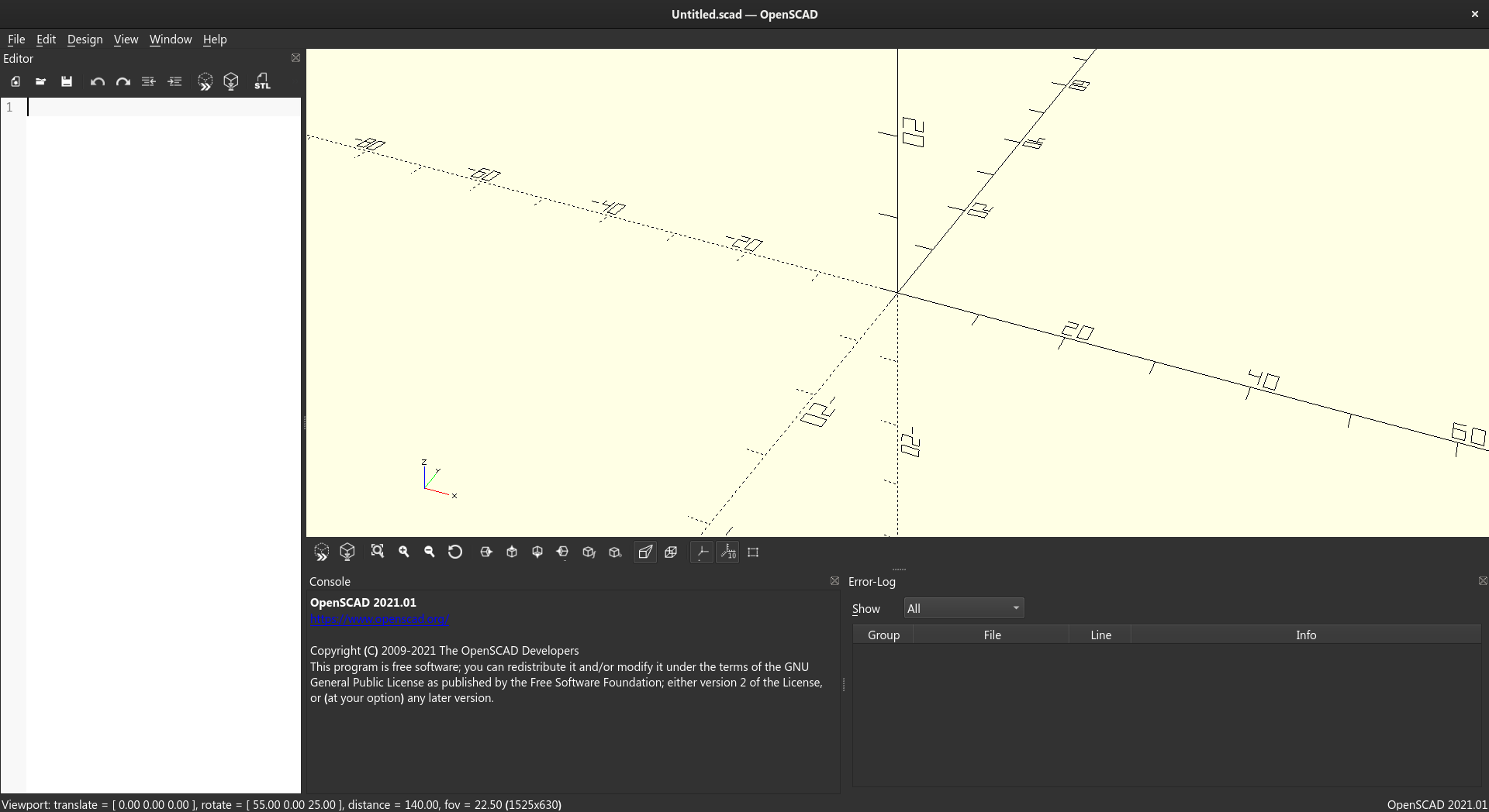
On the left is a text editor, and the yellow area is the viewport. Writing (valid) code in the editor will modify the contents of the viewport. The viewport is also interactive, so you can click and drag to rotate the view.
Cube
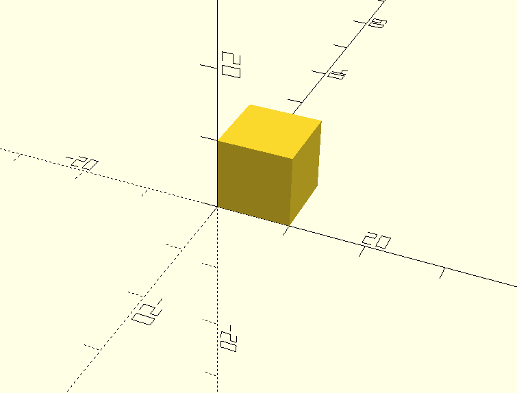
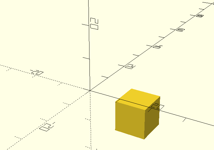
Lets start with some code, starting with a simple cube that has equal side lengths of 10mm:
cube([10, 10, 10]);
Save your file to see the result.
Rectangle
As you may have noticed, we typed 10 three times in the cube definition above. These three entries correspond to the three dimensions of our cube.
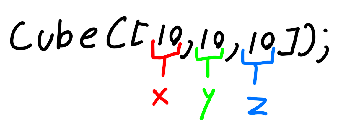
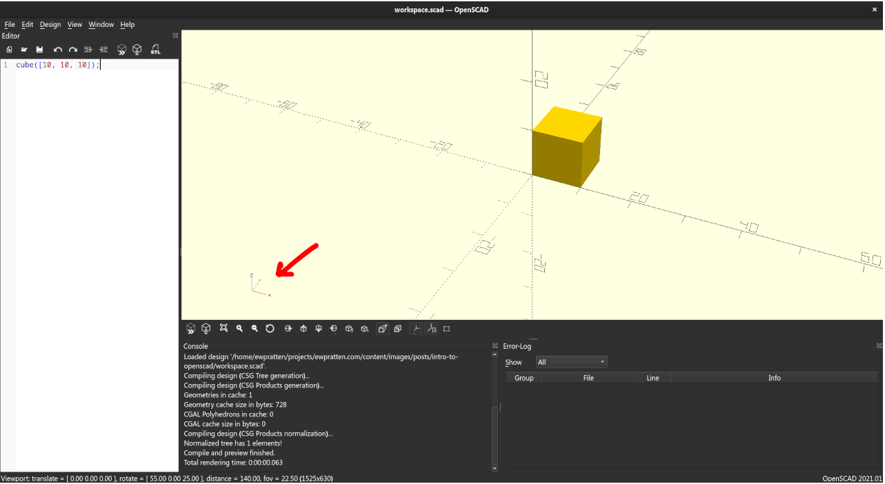
Before we change these values, you should understand OpenSCAD's coordinate system. In OpenSCAD land, the X and Y axes make up the "ground plane", and the Z axis is the vertical axis. You can always reference the little axis gadget in the bottom left corner of the viewport to see which way is which.
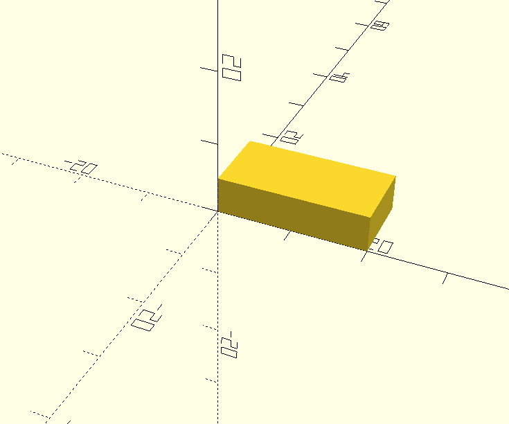
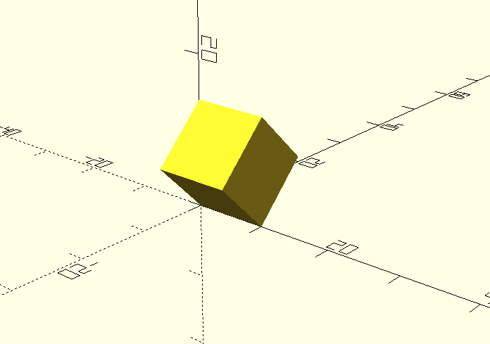
Ok, with the coordinate system in mind, let's make a rectangle. We'll make it 20mm wide, 10mm deep, and 5mm tall:
cube([20, 10, 5]);
Sphere
Spheres are pretty simple. We just need to specify the radius (in this case, 10mm):
sphere(r = 10);

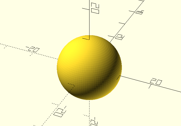
Notice how the sphere is a bit blocky? We can smooth it out by adding an $fn argument to the sphere function:
sphere(r = 10, $fn=100);
The higher the $fn value, the smoother the sphere will be. I like to use 100 for most things. Heres the new result:
Cylinder
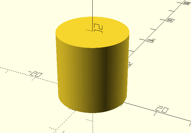
The final shape I'll show off is the cylinder. It works much like a sphere, but takes a height argument in addition to the radius. Here's a cylinder with a radius of 10mm and a height of 20mm:
cylinder(r = 10, h = 20);

Again (like the sphere), we can smooth out the cylinder by adding an $fn argument:
cylinder(r = 10, h = 20, $fn=100);
Transformations
Currently, we have only been able to pace shapes at the origin. This means that adding all of our shapes together into a single file would produce a result with all the meshes overlapping.
// Cube
cube([10, 10, 10]);

// Rectangle
cube([20, 10, 5]);

// Sphere
sphere(r = 10, $fn=100);

// Cylinder
cylinder(r = 10, h = 20, $fn=100);
Translation
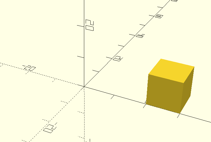
Let's start by moving a shape away from the origin. The following code will place a cube (with side lengths of 10mm) 20mm away from the origin in the X direction:
translate([20, 0, 0]) {
  cube([10, 10, 10]);
}
Notice what happens if we create two cubes, and translate them an equal distance in opposite directions:
// Right Cube
translate([20, 0, 0]) {
  cube([10, 10, 10]);
}

// Left Cube
translate([-20, 0, 0]) {
  cube([10, 10, 10]);
}
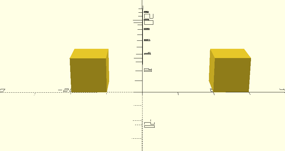
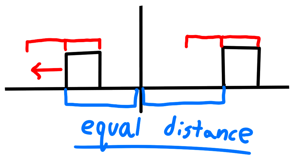
They end up an unequal distance from the origin! This is because cubes (and rectangles) are not centered by default (see the cube or rectangle example above as a refresher).
This means that in order to move that left cube the expected distance away from the origin, we would need to translate it by the original 20mm plus the cube's width (10mm):
// Right Cube
translate([20, 0, 0]) {
  cube([10, 10, 10]);
}

// Left Cube
translate([-(20 + 10), 0, 0]) {
  cube([10, 10, 10]);
}
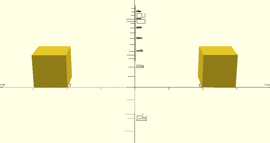
Much better.
Of course, we can also translate objects in all of the axes at once, like this:
translate([5, 6, -15]) {
  cube([10, 10, 10]);
}
Rotation
OpenSCAD rotates objects about an axis. This means that to rotate a cube 45 degrees around the X axis, we could do this:
rotate([45, 0, 0]) {
  cube([10, 10, 10]);
}
Heres an example where we center the cube at the origin, then rotate it 45 degrees in all axes:
rotate([45, 45, 45]) {
  translate([-5, -5, -5]) {
    cube([10, 10, 10]);
  }
}
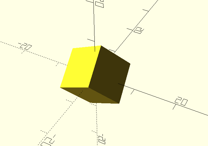
As you can see, individual transformations can be nested together to create more complex transformations.
Cutting & Joining
With some basic prerequisites out of the way, we can start to make more complex shapes. In this section, we'll cover how to cut and join shapes together.
Difference
Lets make a sphere, and punch a rectangular hole out of it.
We can do this with the difference function:
difference() {
  sphere(r = 10, $fn=100);
  translate([-10, -5, -5]) {
    cube([20, 10, 10]);
  }
}
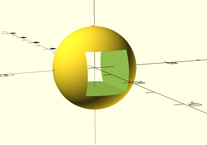
The difference function can operate on multiple shapes. The first shape will always be the displayed shape, and all subsequent shapes will be subtracted from it.
Union
What if we want to join two shapes together, then cut a third shape out of the result?
Since the difference function only shows the first shape given to it, we need to make use of union to join multiple shapes together before cutting them.
difference() {
  union() {
    sphere(r = 10, $fn=100);
    translate([-10, -5, -5]) {
      cube([20, 10, 10]);
    }
  }
  translate([0, 0, -5]) {
    cube([20, 20, 10]);
  }
}
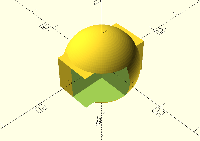
See that weird overhang? Its a render artifact and not actually there in the shape.
To conserve on computation time, OpenSCAD doesn't do an awesome job of rendering really tight tolerances in the viewport. If we want to make it properly compute our shape, we'll have to press the F6 key to render it.
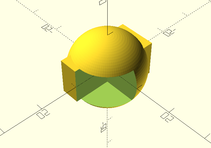
Much better.
Next steps
At this point, you know everything you need in order to create most things you'd want to 3D print.
If you'd like to learn some more complex functions, check out the OpenSCAD documentation.